Linear Hexapod
Overview
Section titled “Overview”The Linear Hexapod is a 6-DoF (Degrees of Freedom) motion platform that uses six linear actuators arranged in a Stewart platform configuration. It provides full motion on all six axes: sway (left/right), surge (forward/backward), heave (up/down), pitch, roll, and yaw. This is the most capable platform type supported by DRSM and is the standard configuration for Departed Reality DIY hexapod builds.
Getting Started
Section titled “Getting Started”- In the Sim Config tab, click the “+” tab to add a new component.
- Select Linear Hexapod (6 DoF) from the dropdown.
- If you are using a Departed Reality hexapod, select the matching preset (e.g., PS400, PS500, or PS600) from the Preset dropdown. The preset loads all dimensions and actuator settings automatically.
- If you are building a custom hexapod, select Custom and enter your measurements manually.
Available Presets
Section titled “Available Presets”- PS400 — Departed Reality 400mm travel actuator layout
- PS500 — Departed Reality 500mm travel actuator layout
- PS600 — Departed Reality 600mm travel actuator layout
- Custom — Enter your own rig dimensions manually
Configuration Parameters
Section titled “Configuration Parameters”Rig Dimensions
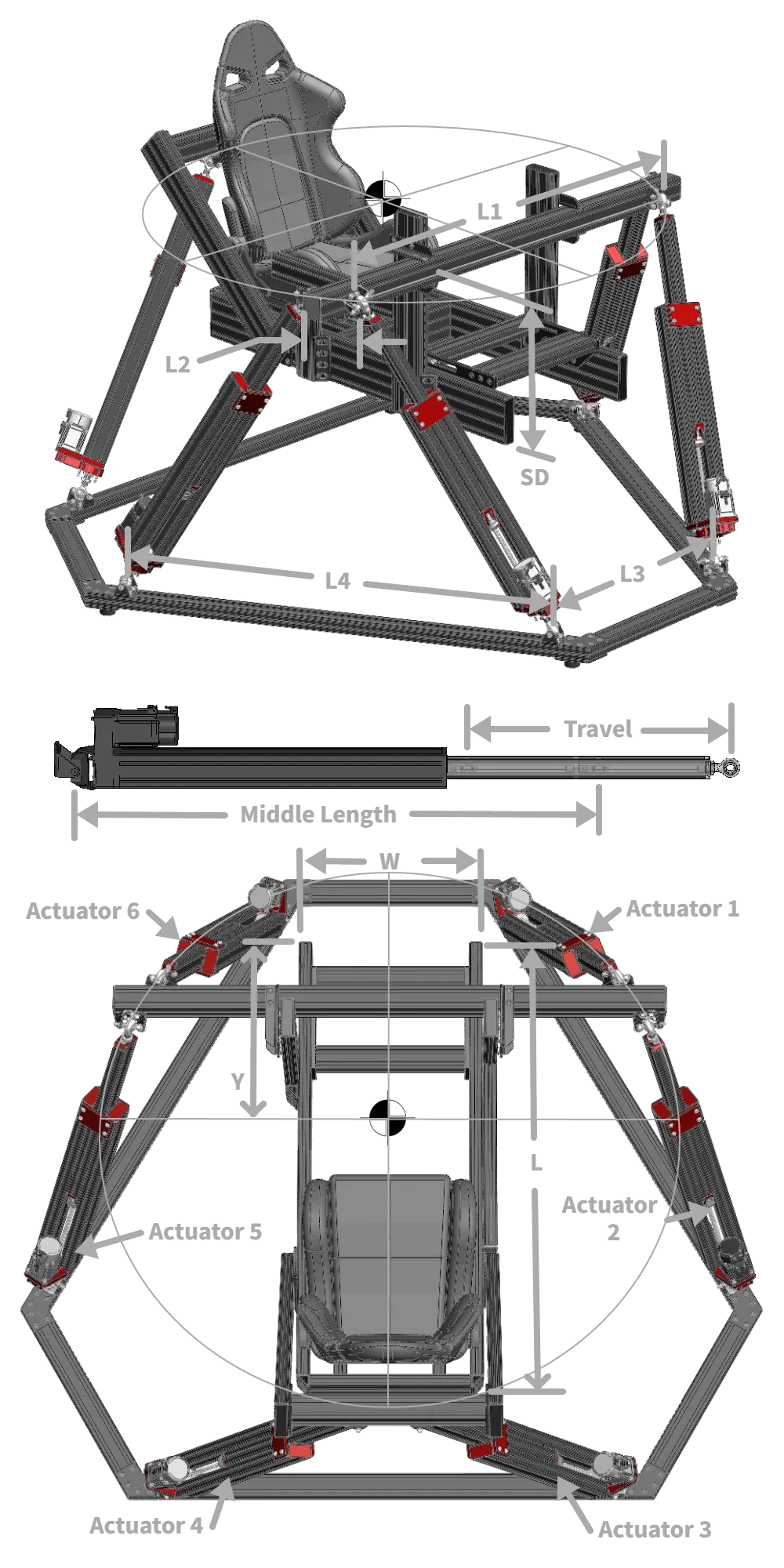
Section titled “Rig Dimensions”These four measurements describe the geometry of the upper (platform) and lower (base) pivot points. They define the triangular arrangement of actuator attachment points on both the moving platform and the fixed base.
- L1 — Upper Distance between Pivots (mm): The longer spacing between adjacent pivot pairs on the moving platform. Measure between the pivot centers on the same side of a pair.
- L2 — Upper Distance between Pivots 2 (mm): The shorter spacing between adjacent pivot pairs on the moving platform. This is the gap between the two pivots in each close pair.
- L3 — Base Distance between Pivots (mm): Equivalent to L1 but for the fixed base frame. The longer spacing between base pivot pairs.
- L4 — Base Distance between Pivots 2 (mm): Equivalent to L2 but for the fixed base frame. The shorter spacing between base pivot pairs.
Actuator Settings
Section titled “Actuator Settings”- Middle Length (mm) — The length of each actuator at its 50% travel position (fully extended minus half the total stroke). This is the neutral resting length that defines the platform’s home height.
- Travel (mm) — The total stroke distance of each actuator from fully retracted to fully extended. For example, a 500mm travel actuator moves 250mm up and 250mm down from center.
- Overallocation Factor — Controls how aggressively DRSM uses actuator travel when multiple axes move simultaneously. See Overallocation Factor for details. Default: 2.00.
Travel Limits
Section titled “Travel Limits”These set the maximum range of motion the platform is allowed to use on each axis. DRSM calculates the actual achievable limits from your rig geometry, but you can restrict them further here.
Linear Motion (mm)
Section titled “Linear Motion (mm)”- Sway — Maximum lateral (left/right) displacement from center
- Surge — Maximum forward/backward displacement from center
- Heave — Maximum vertical (up/down) displacement from center
Angular Motion (degrees)
Section titled “Angular Motion (degrees)”- Pitch — Maximum forward/backward tilt angle
- Roll — Maximum side-to-side tilt angle
- Yaw — Maximum rotational angle
Collision Prevention (Experimental)
Section titled “Collision Prevention (Experimental)”Enables real-time detection of potential collisions between actuators and the cockpit structure. When a collision is detected, DRSM limits motion on the offending axis to prevent contact.
Cockpit Dimensions
Section titled “Cockpit Dimensions”- W — Platform/cockpit width (mm): The side-to-side width of your cockpit structure
- L — Platform/cockpit length (mm): The front-to-back length of your cockpit structure
- SD — Sunken depth (mm): How far below the platform surface the cockpit extends (the depth of the cockpit “tub”)
- Y — Vertical offset (mm): The vertical offset of the cockpit relative to the platform pivot plane
- Actuator Diameter (mm): The physical outer diameter of your actuator cylinders, used for clearance calculations
Setting Up Collision Prevention
Section titled “Setting Up Collision Prevention”- Enable Collision Prevention in the Sim Config panel.
- Measure your cockpit dimensions and enter them.
- Set the Actuator Diameter to approximately 100mm larger than your actual actuator diameter. This provides a safety margin.
- Test with Manual Control first — Use the Manual Control source and sweep each axis through its full range. Verify that collision prevention activates before any physical contact would occur.
- Adjust the Actuator Diameter value up or down to fine-tune the safety margin.
Common Mistakes
Section titled “Common Mistakes”- Swapped L1/L2 or L3/L4 — If the platform moves in unexpected directions or has very limited travel, you may have the short and long pivot distances swapped. L1 and L3 are the longer distances; L2 and L4 are the shorter ones.
- Incorrect Middle Length — This must be the actuator length at the 50% travel point, not the fully extended or fully retracted length. An incorrect value causes the platform to sit at the wrong height and may reduce available travel.
- Travel limits too aggressive — Setting axis limits larger than the rig can physically achieve causes overallocation warnings and jerky motion. Start conservative and increase gradually.
- Collision Prevention without testing — Always test collision prevention with Manual Control before using it with games. A misconfigured cockpit dimension can either restrict motion unnecessarily or fail to prevent actual collisions.
Verifying Your Setup
Section titled “Verifying Your Setup”- Use Manual Control — Select “Manual Control” as your source and use the sliders to move each axis individually. Verify smooth motion across the full range.
- Check the 3D Visualizer — Open the 3D Visualizer dock to see a real-time representation of your hexapod geometry. Compare it to your physical rig — the actuator arrangement and platform shape should match.
- Sweep each axis to its limits — Move each axis to its maximum positive and negative values. The platform should reach a clear mechanical limit without binding, and the actuators should not hit their end stops.
- Test combined motion — Move multiple axes simultaneously to verify the overallocation factor is working correctly. If you see overallocation warnings in the log, reduce your travel limits or increase the overallocation factor.